Thursday, February 21, 2019

Game Boy Emulator On STM32, over composite video (with sound)

Final Result


The ManWorm TV

Over the past few months, Bayley and I have been working on the MANWORM TV.  The MANWORM TV has a STM32F446RE microcontroller connected to an 4-bit resistor DAC and a buffer, for generating composite video signals.  We have developed simple games (pong, racing, wolfenstein clone), 3D graphics (vector and raster), and even a program to play back video from an SD card (it once played back all of Star Wars Episode IV).

Here's what it looks like:

The NTSC video format is a series of horizontal scans, each approximately 63 microseconds long.  Each line begins with a sync pattern and is following by the video data.  A higher voltage indicates a brighter white.  To generate the waveform on the microcontroller, an interrupt is configured to go off every 63 microseconds.  The interrupt loops through all the pixels in the line and changes the output voltage.  The timing between pixels is achieved by inserting a few NOP instructions - there are only a few hundred nanoseconds between pixels!  There are two major drawbacks to this approach.  To start with, drawing the full screen takes almost all of the CPU time, giving you no time to generate image data. In practice, I get around this by truncating lines early, giving you around 20 microseconds of free CPU time per line, and by having a more efficient way of generating the all-black lines that are offscreen and near the bottom.  Notice that the Star Wars demo uses only a small fraction of the screen to be able to copy data from the SD card in time.  You basically are required to use double-buffering, which uses more than half the RAM on the microcontroller.  

 The second drawback is that the amount of time it takes to enter the interrupt and load the ISR into icache can be somewhat variable, causing some weirdness.  You can see this most clearly in the Star Wars video.

Gameboy Emulator

One day, I was bored and decided to try writing a gameboy emulator.  One weekend and ~20 hours of programming later, I was playing Pokemon.  

Part 1

The Gameboy CPU is custom, but similar to both the Z80 and the Intel 8080.  It has an 8-bit accumulator register, a 16-bit stack pointer register, a 16-bit program counter, and 6 other 8-bit registers, which can sometimes be used in pairs as a 16-bit register.  It has 8 kB of internal RAM, 8 kB of VRAM, as well as additional RAM and ROM in cartridge.  


The first step to writing the Gameboy Emulator was to write the memory and cpu subsystems.  There are several types of Gameboy Cartridges, which contain the game data, stored in (possibly multiple) ROM banks, as well as additional RAM.  The memory system keeps track of which memory banks are currently mapped, and can do reads/writes of gameboy memory.  The memory layout is roughly as follows:
  • 16 kB ROM bank #0 (always mapped to this bank, contains Interrupt handlers)
  • 16 kB switchable ROM bank
  • 8 kB VRAM (stores tiles)
  • 8 kB switchable RAM bank (cartridge RAM)
  • 8 kB internal RAM
  • Mirror of 8 kB of internal RAM
  • 160 bytes of Sprite Attribute Memory (where each sprite should be)
  • Various registers
  • Fast Top RAM (used for stack)
  • Interrupt Enable byte

In my first pass, I did not implement any of the registers and only implemented internal memory.  


Next, I started writing the CPU emulator.  The Gameboy has around 512 opcodes.  256 of them have a single byte indicating  what the opcode is, followed by a few bytes of arguments.  The remaining 256 opcodes start with byte 0xCB then have a second byte indicating the function.  The CPU emulator I started with uses the following approach
  • increment the DIV register (increases at 16 kHz)
  • Read the opcode at PC
  • Interpret the opcode at PC (does the function of the opcode, increments PC, increments the cycle count, which is different for different instructions)

Finally, I set up the video system emulator.  It is updated after every single emulated instruction and is told how many emulated cycles have elapsed.  The video system writes to the display line-by-line and is timed off of the CPU clock.  I implemented a few of special registers which tell the CPU what line is currently being drawn.

After all this, I was able to partially emulate the Gameboy BIOS, which would normally display the nintendo logo.  Without video, it was challenging to verify it was actually working, but I was printing each write to the video SCROLLY register, which showed that the CPU was decrementing this register to zero, waiting around a second, then attempting to jump out of the BIOS.

Part 2

The next step was to implement more CPU instructions, like the shifts, bit sets/clears/checks, fix a few bugs in setting various flag bits, and add in interrupts.  When going into an interrupt, the address to return to is pushed onto the stack, and the PC jumps straight to the interrupt handler.  There is a master enable/disable of interrupts accomplished with the EI and DI instructions, as well as an interrupt mask byte.  The first interrupt I added was the V-Blank interrupt, which runs 60 times per second, when the video RAM is not being used by the display hardware and can be accessed.  Here's what the main CPU step function looks like:

I also added a frame buffer and display window with SDL.  It displays the framebuffer as an SDL texture.  SDL was also used for reading the keyboard, which also triggers an interrupt.  The Gameboy uses a scan matrix to determine which keys are pressed.

At this point, I also implemented the background render.  The VRAM is filled with tile data, as well as a tile map, which tells you which tile should go in which spot.  There are also SCROLLX and SCROLLY registers, which allow you to scroll the background around (it wraps!).

After a few issues with bit-shifting operations, I was able to get the following:

Notice that the (R) is a bit corrupt.  This is because the Gameboy BIOS ROM I copied from the internet is slightly corrupted...  

I was also able to run the "blargg CPU instruction test ROM", which showed that there were still many bugs in the CPU emulation and would crash before running all tests:

Part 3

In round 3 of Gameboy Programming, I fixed more CPU bugs, implemented some ROM bank mapping, implemented the DMA function, added the sprite renderer.  This let me play Tetris, though the colors were still wrong:
I could also run the entire CPU instruction test without crashing the emulator, though several instructions still failed.

Part 4

After fixing a few more CPU bugs, implementing the HALT instruction (suspend until next interrupt), and adding the programmable timer, I was able to boot Dr. Mario.  There were still a few bugs related to tile maps and sprite transparency that needed fixing:


Part 5

Next up was a rewrite of the ROM/RAM banking system to be more flexible.  I finally revisited the graphics, fixing the tiles, adding the window renderer, and implementing palettes/transparency.  Here's what the memory banking code looked like: There were still a few small bugs, but it was good enough to start pokemon:

Part 6

Finally, Pokemon was working correctly. Here's the drawLine function, which draws a single line onto the screen:


This code is available on github from here:
https://github.com/dicarlo236/gameboy

It doesn't run every game, but seems to be pretty good with the games that it does.  There are two known bugs with this version: The button reading emulation is slightly wrong, causing some games like Pokemon Green to have trouble and some of the video registers are wrong, causing the move CONFUSION in pokemon to get stuck forever.

Part 7 - On to the STM32F446RE!

The next step was to port the emulator to the microcontroller.  I wrote the code knowing that I'd have to do this port, so it was pretty straightforward.  From the beginning, it was clear that this would be a struggle - I needed to remove the bitmapped font in order to have enough memory to store everything.  There were problems with both RAM and flash size - there simply wasn't enough flash storage to store pokemon red, and I didn't have enough RAM to do double buffering.  Despite this, I got the gameboy code booting in around 20 minutes, though it was extremely slow.  I implemented a number of tricks to speed up the game:
  • Only output frames at ~10fps
  • Improve the DMA and tile reading functions to be much faster (use memcpy instead of for loop which uses gameboy memory subsystem)
  • Skip cycles when the CPU is in halt mode, but this does cause timing issues in some games
As you can see, the quality of the image is poor, and we are limited to running games which have a small ROM, small RAM, use the halt instruction, and are not CPU intensive.  Tetris ran much slower.
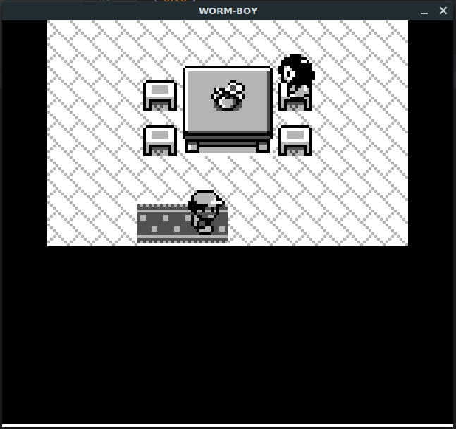
Part 8 - Pokemon?

I spent a lot more time improving the speed of the emulator, mostly related to graphics and more intelligent cycle skipping.  I was able to shrink some video buffers down in size to give me enough RAM for pokemon, but I did not have enough memory to store the game in flash.  To get around this, I broke up the 1 MB ROM into a bunch of pages, then stored as many as possible of the most commonly used pages in flash.  I then used the remaining 32 kB of RAM on the nucleo and an SD card to implement a caching system that would load in pages from the SD card as needed, then store them in the RAM cache until another page needed the same spot.  I got the best performance when making the pages the same size as the SD card read block size.  The best cache design used a hash table with a limited-length linear probing scheme, with LRU replacement (it did limited length linear probing, then replaced the entry least recently used in the probe).  Unfortunately, there are simply some sequences in Pokemon which require tons of bank switches, meaning I need to read from the SD card incredibly often.   Some basic timing calculations showed that it was unlikely pokemon would ever run at full speed using this technique, but it did work:


Here's the function that was used to read a byte from the ROM

Part 9 - A Better Microcontroller

The solution to my speed problem is to switch to a better microcontroller.  Bayley recently purchased some STM32H7 dev boards, which have a roughly 2x faster clock, and have enough flash to store all of Pokemon Red.  However, this meant porting all of the Gameboy and NTSC video code from the MBED online compiler to the AC6 Workbench, learning how to do interrupts on the H7, and making another DAC out of some resistors and a random op-amp.  I didn't know it at the time, but I was mistakenly programming the H7 in some sort of debug mode (even though I compiled with -O2...) which gave it around a factor of 3 decrease in performance.  Even then, the performance improvement was huge.  Pokemon was now much closer to real time (running at 60 fps!), and simple games like Mario Land and Dr. Mario were running at full speed!  I also implemented the sound subsystem of the gameboy, and used a "1-bit DAC" (aka a digital output pin) to play back the music.  

The sound was very bad, so I switched to the built-in DAC, which improved things a lot.  There are a number of hacks to get the sound working (the arbitrary waveform is always a triangle, the noise channel is greatly simplified...) but the trick to getting a nice sound is to run the sound interrupt inside of the video interrupt.  This only gives us 15 kHz sampling, but it's not the end of the world.

Here's a video showing the progression of the sound system, from absolutely terrible to halfway decent:


Here is the sound code for channel 1 (the others are pretty similar) and the sound interrupt code:

Part 10 - A better video routine

The H7 has a very fancy DMA system which Bayley realized might help with the video code.  The idea is that you set up a timer to run at 8 MHz (this gives us 512 pixels per line) to clock the DMA output.  The DMA can then be configured to output an entire horizontal line independently from the CPU, then trigger an interrupt at the end.  This interrupt would then reload the DMA for the next line.  Because the line-end interrupt happens at 15 kHz, we can also use it to compute the sound DAC output voltage and get reasonable quality sound.  Getting the DMA up and running took most of a day, but the results were very good:


In this video, I am still running in the reduced performance debug mode, but you can see the "lag" counter which displays how many frames behind (or ahead, if it's negative) of real time we are. 

Here is the DMA NTSC code:

Summary

In total, the project is 6,023 lines long, of which 1,515 are blank/comments and 4538 are actual code.  The largest files are

  • gb_cpu: 2,445 lines
  • gb_mem: 678 lines
  • gb_sound: 369 lines
  • gb_video: 309 lines

Wednesday, March 7, 2018

Rubik's Solver Software

Recently, Ben Katz and I collaborated on a Rubik's Cube solving robot to try to beat the world record time of 0.637 seconds, set by some engineers at Infineon.  We noticed that all of the fast Rubik's Cube solvers were using stepper motors, and thought that we could do better if we used better motors.  So we did:


Our solve time of 0.38 seconds includes acquiring the image from the webcam, detecting colors, finding a solution, and actually rotating the faces of the cube.  In the video, the machine is solving a "YJ Yulong Smooth Sitckerless Speed Cube Puzzle", available on Amazon for $4.55.  We used the cheapest cube we could find on Amazon Prime because we thought we'd end up destroying many of them, but somehow ended up only going through 4 cubes and 100's of solves.


Ben made a blog post that describes the hardware and build as well as the insane nonlinear minimum-time sliding mode controller which let us do 90 degree moves in around 10 ms.  We used Kollmorgen ServoDisc motors, which have a very high torque-to-inertia ratio.  The motor is coreless, so there are no heavy steel laminations on the rotor, and there's no steel to saturate, so it can accelerate insanely fast.  In a 10 ms quarter-turn move, the motor reaches over 1000 rpm. 

On the software side, I used OpenCV for the color detection and this fantastic implementation of Kociemba's Two-Phase algorithm called 'min2phase' .  We used Playstation 3 Eye webcams, which are only $7 on Amazon Prime, and work at 187 fps under Linux.  The software identifies all the colors, builds a description of the cube, and passes it to the min2phase solver. The resulting solve string is converted to a compact cube sequence message, and is sent to all motor controllers simultaneously using a USB to serial adapter connected to a differential serial IC.  This whole process takes around 45 ms.  Most of the time is spent waiting for the webcam driver and detecting colors.  All our software is on GitHub here: https://github.com/dicarlo236/cube-solver


The motor controllers step through the moves one by one and remain synchronized with the AND BOARD, which tells all the motor controllers when the current move is finished. 


Sunday, February 18, 2018

Programming an ATMEGA328PB with avr-gcc

Atmel/Microchip have recently released the ATMEGA328PB, a microcontroller that's very similar to the ATMEGA328B commonly found in Arduinos.  The new features are:

  • Slightly lower price
  • Two more good timers
  • Extra UART, SPI, and I2C
  • 4 more PWMs
There are some major drawbacks though
  • No more full-swing crystal oscillator
  • Didn't work with the Arduino IDE when I tried
  • Most toolchains don't support it yet out of the box
To program it with avr-gcc and avrdude requires a few extra steps.  These steps are written for a Linux development computer and a usbasp programmer.

The first step is to download and install the usual versions of avrdude, avr-gcc, avr-objcopy, avr-binutils, and avr-libc.  On Ubuntu, these are all packages that can be installed with apt.

The version of avrdude I have (6.2) didn't know about the 328pb, so I had to modify the avrdude.conf file.  On my install of Ubuntu 16.04, this was in /etc/avrdude.conf.  At the bottom, I added the lines:


part parent "m328" id = "m328pb"; desc = "ATmega328PB"; signature = 0x1e 0x95 0x16; ocdrev = 1; memory "efuse" size = 1; min_write_delay = 4500; max_write_delay = 4500; read = "0 1 0 1 0 0 0 0 0 0 0 0 1 0 0 0", "x x x x x x x x o o o o o o o o"; write = "1 0 1 0 1 1 0 0 1 0 1 0 0 1 0 0", "x x x x x x x x x x x x i i i i"; ; ;


which I got from here: https://lists.nongnu.org/archive/html/avrdude-dev/2016-06/msg00010.html

This is the same as the normal 328b, but has the correct device signature for the 328pb.  As far as I can tell, the device signature is the only difference between the two.

Next, we need to download a "pack" from Atmel's that tells gcc about the 328pb.  I downloaded the Atmel ATmega Series Device Support Pack from packs.download.atmel.com 

I had to copy all the *.h files from within the pack to /usr/lib/avr/include to get the avr io headers to work properly.  I also put all the other files from the pack into a folder called `packs` in my project folder.  Inside the packs folder should be folder like "gcc, include, templates..."

Now we can program the microcontroller:

First, compile the code with

avr-gcc test.c -DF_CPU=1000000 -mmcu=atmega328pb -c -B packs/gcc/dev/atmega328pb/

then, create an ELF then intel hex file with

avr-gcc -o test.elf test.o -DF_CPU=1000000 -mmcu=atmega328pb -c -B packs/gcc/dev/atmega328pb/

avr-objcopy -O ihex test.elf test.hex

finally, program the microcontroller.  This command attempts to set a very low programming clock speed to be safe.

avrdude -c usbasp -p atmega328pb -B 60 -U flash:w:test.hex


Debugging with GDB on an mbed STM32 Nucleo

Having a real debugger is incredibly useful, and it turns out it's not too hard to get GDB working on the STM32 Nucleo development boards with Linux. It's also a nice and very fast way to load code onto the Nucleo with no internet connection required.  Here's what I did to get debugging working on my Nucleo.

First, we need to install the compiler, debugger, openOCD, and make:

sudo apt install make gdb-arm-none-eabi gcc-arm-none-eabi openocd

To get the makefile and mbed libraries, I created a new project on the mbed compiler website, right clicked on the project in the tree on the left, and exported the project as "Make_gcc_arm", and unzipped the file.

Next, we need to retrieve the configuration files for the board and its interface.  On my computer, the openOCD script files were stored in /usr/share/openocd/scripts.  The file for the ST-Link is interface/stlink-v2-1.cfg, and the file for the micro itself is board/st_nucleo_f4.cfg.  I copied these two files to my project folder.


The default Makefile doesn't turn on debugging symbols, so it needs to be modified.  In the "Tools and Flags" section of the makefile, I added a '-g' flag after 'arm-none-eabi-gcc' for CC and CPP.  I ran make, which complained about clock-skew, but produced a BUILD folder with bin, elf, hex, and .o files. 

Next, we need to set up the connection between the ST-Link and the computer.  This is done with openOCD (on-chip-debugger).   OpenOCD must be started in the folder where you've copied the .cfg files for the ST-Link and the board.  To start the program, run


sudo openocd -f st_nucleo_f4.cfg -f stlink-v2-1.cfg -c init -c "reset init"


There may be an "already specified hl_layout stlink" error, but this shouldn't cause a problem.  You should see near the end of the output "target state: halted", the 3.3V supply voltage, and a few of the CPU registers.

Next, we need to run gdb with `arm-none-aebi-gdb`.  You should do this in the project folder - the one which has the BUILD folder in it.  To connect to OpenOCD, run `target remote localhost:3333`.  Next, we need to tell gdb which program we are trying to debug by running `file BUILD/project_name.elf`.  It may warn you that there is a program being debugged already, but you should press 'y' to force gdb to load the debugging symbols for the most recent build.  

The next step is to get the microcontroller ready to receive the program.  Sometimes you can get away with skipping these steps.  Run 'monitor reset' then 'monitor halt' to put the micro in a good state.  

Now we can load the firmware onto the microcontroller by running 'load'.  If at any point you change the source, all you need to do is run make, then run 'load' from gdb.  If the nucleo goes into a bad state, you can reset it with the 'monitor reset' command in gdb.

To start running the program, run 'continue'.  Surprisingly, almost every feature of GDB actually works in this setup.  I can view and modify local variables, arguments, and globals, can view registers, can use the hardware breakpoints and watchpoints of the microcontroller, and can pull up the source code for some of the mbed libraries as well.

Sunday, November 12, 2017

Composite (NTSC) Video on mbed Nucleo (stm32f401)


This weekend, I put together a demo program for an STM32F401 development board that generates a composite video output.  My development board didn't have a DAC, and I needed three different output levels, so I used two digital output pins and resistors.  This solution isn't incredibly robust - different monitors and displays require slightly different resistor values to function correctly.  I found that a ratio of around 1 to 2 worked pretty well.  The SYNC pin should generate a 0.3V signal at the composite input, and the SYNC and VID pins should generate a signal in the range of 0.7 to 1.0V at the composite input.


The goal of this project was to generate NTSC video output using only the mbed libraries.  I'm sure it's possible to do a much better job if the timers and interrupts are configured manually, but that's a lot of work...  To learn about NTSC, I used this PDF (link).  The basic idea is that each horizontal line begins with a synchronization signal, followed by the data for that line.  Each line is around 63 microseconds long, meaning you'll need more than 1 microsecond timing resolution if you want more than 63 horizontal pixels.  After all the horizontal lines are scanned, including a few bonus ones that don't end up shown on the screen, there is a vertical sync pattern, which starts the entire process over. The sub-microsecond resolution turned out to be quite an issue - mbed timing functions are based off of 1 microsecond timers, so I needed to get creative. Also, the mbed "Ticker" class fails to time accurately (around 20 microseconds of jitter) if more than one Ticker is in use, so I could have exactly one accurate source of timing. 


Here's what a single horizontal line looks like:
The vertical sync pattern is quite complicated:

Getting the v-sync timing reliable on multiple monitors turned out to be incredibly challenging, so I eventually wrote a stupid program which slowly adjusts the waveform, and just watched the screen until it worked.  I found that a much simpler v-sync pattern was sufficient.

Due to the 1-microsecond resolution limit of the default mbed library, I was unable to set up per-pixel timing.  Horizontal line timing used a Ticker running every 63 microseconds.  This is slightly faster than the 63.5 microsecond NTSC standard, but it seems to work.  64 microseconds did not.  The ISR is surprisingly simple:

void isr()
{
//SETUP
    uint8_t nop = 0; //use nops or use wait_us
    uint8_t* sptr; //pointer to sync buffer for line
    uint8_t* vptr; //pointer to video buffer for line
    if(l < V_RES){ vptr = im_line_va + ((l/4)*H_RES); sptr = im_line_s; nop = 1; } //pick line buffers
    else if(l < 254){ vptr = bl_line_v; sptr = bl_line_s; nop = 0; }
    else{ vptr = vb_line_v; sptr = vb_line_s; nop = 1;}
    uint8_t lmax = nop?H_RES:12; //number of columns
//DISPLAY
    for(uint8_t i = 0; i < lmax; i++) //loop over each column
    {
        vout = vptr[i]; //set output pins
        sout = sptr[i];   
        if(nop) //nop delay
        {
            asm("nop");asm("nop");asm("nop");asm("nop");asm("nop");asm("nop");asm("nop");//asm("nop");asm("nop");asm("nop");asm("nop");asm("nop");asm("nop");asm("nop");asm("nop");asm("nop");
        }
        else {wait_us(1); if(i > 2) i++;} //wait delay
        
        
    }
    //move to next line
    l++;
    if(l > 255) l = 0;
}


The ISR gets slightly more complicated because it uses two different timing strategies:

  1. "nop": A number of "nop" instructions are run, delaying for an exact number of CPU cycles.  This is very accurate, but hogs the CPU and prevents other contexts from running.
  2. "wait_us":  This is low resolution (can only do multiples of 1 us, which is 1/60 of a horizontal scan), and low accuracy (sometimes waits too long).  With only this method, I managed to get 18 horizontal pixels.  However, it allows other tasks to run in the background while it is waiting - a modern microcontroller can do a ton in 1 microsecond.


There are three cases for setup:

  1. The line number is less than the vertical resolution.  If this is the case, store the memory location of the current line of the image buffer in vptr, and store the memory location of the video synchronization pattern in sptr, and choose the "nop" timing.  More on this later.
  2. The line number is greater than the vertical resolution, but less than 254. In this case, prepare to display the blank patterns for video and sync.  Don't use "nop" timing, and use a horizontal resolution of 12.
  3. The last line: prepare for vertical sync.

In the display section, the video data loaded into vptr and sync data loaded into sptr are written to the VID and SYNC pins.  When important data (vertical sync and the actual video) is being sent, timing is done with a series of "nop" instructions.  For the less important signal (displaying "blank" on the bonus lines that don't show up on the screen), timing is done with a wait_us(1) command.  These wait_us(1) commands are very important - when using nop timing, the ISR takes around 62 microseconds to execute, leaving almost no time for other processing to be done. During the wait_us(1) command, the microcontroller is free to switch contexts and execute other code.  The wait_us function is terrible, and occasionally waits 2 or even 3 microseconds, so the horizontal resolution has to be reduced to 7.  This low resolution would look terrible when displaying video, so we can only use this trick when the stuff being drawn is off screen.


In the background, the microcontroller is busy updating the image buffer to display other items.  I have implemented code to translate and rotate 3D points, draw lines between points, draw checkerboards, draw simple bitmapped images, and calculate the position of a very simple bouncing ball (inspired by this).

Sadly, none of the rest of the code can use any sort of timing because the performance of the mbed Ticker class becomes too poor to have a stable video output when multiple Tickers are running, so it is adjusted to be more or less efficient so that the demo runs at a reasonable speed.  This involved doing all sorts of terrible modifications, compiling, loading, testing, and readjusting.  I don't know what compiler is used by the online IDE, other than it isn't gcc (or at least the error messages don't match gcc), and I suspect that it compiles with no optimization flags, so some code includes optimizations I'd normally rely on the compiler to do, and some code is intentionally not optimized to run more slowly.  For whatever reason, the code to generate the checkerboard was incredibly slow compared to everything else, including lots of floating point math used to rotate the cube and draw lines.  In the end, the version that was fast enough, but not too fast, looked like this:


void draw_v_check(int8_t r,uint8_t tt)
{
    for(int i = 0; i < H_RES; i++)
        for(int j = 0; j < V_RES; j++)
im_line_va[i+j*H_RES] = (((i > 20) && (i < 98)) && ( tt ^(((j%(r*2))>=r) ^ ((i%(r*2)))>=r)));
}

In the end, the silly demo looks like this:


 and the full code, including a very poorly-written demo:
https://github.com/dicarlo236/mbed-video/blob/master/main.cpp


Lesson learned: Don't use the mbed libraries for things that require complex timing!  This code is a disaster.

Thursday, September 21, 2017

Playing MIDI on an STM32F446 Part 1: Square Waves

I've decided to try to make an 8-bit style music player out of a microcontroller. There are some really cool arduino versions of this project, but they all seem to require a very confusing custom file format to describe the song. My goal is to use a simple format that can be easily generated from a midi file.  As a proof of concept, I wrote some code which plays a midi file converted to a list of note data in the format "start time, duration, pitch, volume".

This version has a known issue with high pitch notes. If a note requires a duty cycle of 80.5 DAC cycles, it will just round down to 80 cycles, which makes it sound flat. Instead, it should alternate between 80 and 81.

Eventually, I plan to add more sounds and effects other than "square wave with 50% duty cycle", but for now, that's the only choice. The plan is to make each instrument kind of like a script. Each instrument would have an array of function pointers and arguments which get executed in order. Functions could do things like "delay 20 instrument cycles", "set output to triangle wave", "increase pitch by major third", "do a vibrato effect", or even "move function pointer array pointer back n steps".

I plugged the DAC into my computer's line in port, and recorded this:
https://www.youtube.com/watch?v=bGQ_Zj2jo8s

Saturday, July 22, 2017

Hoverboard Robot Arm Part 1: The Class Project

I decided to build a robot arm for my 6.115 final project, which, in retrospect was a bad idea.  The project is open ended, but requires you to use an Intel 8051 and a Cypress PSoC microcontroller.  The 8051 is from the 1980's and is useless, and the PSoC is only there because Cypress gave MIT a ton of money.  The PSoC is honestly a very bad microcontroller - it's neither high performance nor cheap, but it's still way better than the 8051.  It's unique feature is that there's some sort of vaguely FPGA-like thing that allows certain pins to be remapped.  As a result it does many things, but nothing well.  It is very slow at floating point math.  The analog inputs are slow.  It can literally do half the PWM and encoder decoding of the similarly priced ST micro.  It has no hardware serial support.   Cypress donated development kits, so the class uses PSoC microcontrollers as the example of modern microcontrollers.

At least in my opinion, most project-based classes involve projects that are on the boring side, and are technically not that interesting.  6.115 is the exact opposite - the final projects are supposed to be very ambitious.  My original final project proposal included the following

  1. Designing a 3-phase inverter capable of running at 400V, 20A with low side current sensing
  2. Laying out a PCB for the motor controller
  3. Populating/debugging the PCB
  4. Implementing field oriented motor control for torque control of a brushless motor
  5. Designing a discrete-time current controller
  6. Characterizing a motor from an electric hoverboard
  7. Designing a full state feedback controller for robot arm endpoint position control
  8. Implementing code to compute the robot arm's Jacobian to have force control of the robot arm
  9. Designing and fabricating an extremely low inertia, direct drive robot arm
  10. Simulating the robot arm force/torque control in MATLAB
  11. Writing a motor simulator to test the field oriented control logic
  12. Coming up with a robust communication protocol for the motor controller to talk to the 8051
  13. Hooking the 8051 to the timer chip, the serial chip (to talk to the motor controller), two ADC's (for controlling the robot arm), a keypad encoder (for changing settings), and one of those Hitachi displays (for showing position error)
which pretty much hit everything covered in the class (motors, current control, first order circuits, feedback control, switching regulators, feedback control of switching regulators, stepper motors, digital signal processing, digital filters, and characterizing systems).  The suggestion was to add code that takes in a JPEG, vectorizes it, then draws the image.  On an Intel 8051.  


This project was submitted as a "safe" robot arm with "small" electric motors, driven by "little 3 phase inverter ICs" powered from a "low-power" bench supply. There's a huge number of safety requirements for the project, which is pretty reasonable given some of the proposed ideas. The "safe" and "small" motors are around 1.5 kW motors from an electric hoverboard, the "little" IC is actually a 75A, 600V IGBT in a package that can dissipate 225W, and the "low-power bench supply" is, well, actually a completely reasonable 3A, 15V bench supply that we're required to use.

We were taught in class that using words like "low-power" or "large" were relative and meaningless in engineering, so I didn't feel too bad about submitting the robot arm.  For the project checkoff, I ran the arm with a power supply limited to ~5 watts, and had somebody inspect the arm to make there wasn't a hidden boost converter with dangerously high voltage, so it wasn't like there was actual danger.

Building the Arm

Bayley recently bought 15 hoverboards from a man in New York, and gave me a few motors to use for this project.  I started by removing the tire from the motors and disassembling.

There's a lot of motor inside!  Unfortunately, I couldn't come up with a clever way to hide an encoder on the inside of the motor, so I bored a hole in the casing to give me access to the fixed shaft from the front of the motor.  There aren't very many circular features on this motor, so finding the center is challenging.  I ended up putting it in a four-jaw chuck on the lathe, but was only able to get within .001" because nothing on this thing is actually round.  

During the next week, I made all the brackets and clamps.  Some were made on the MITERS CNC
and other were made on the Haas VF-2 next door

The last three parts were done on all manual equipment because the CNC's were in use

After a week of machining, I had bunch of shiny aluminum parts

Next,  I found some thin wall tube laying around MITERS and assembled the two arms


Electronics

The controller for this arm is overkill.  The IGBT module (FNA27560) is good for 50A, 400V continuous with good heatsinking, so it's more of an electric vehicle controller than a robotics controller.  I created a schematic inspired by the reference design for the IGBT module and added a microcontroller and differential serial.  There are no power supplies on the board.  I'm not sure if this was a good decision or not, but I planned to put the 5V, 3.3V, 15V supplies on a separate board that connected to both boards.  Unfortunately, I wasn't allowed to use the ST microcontroller for the class project as the class was bought out by Cypress and forbids knowledge of other companies has received generous donations of money and parts from Cypress.  Instead I was forced to decided to take advantage of the Cypress Programmable System on a Chip 5LP microcontroller development platform, and created a controller that was in every way worse than the ST based controller was easy to implement with the Cypress "PSoC Creator" software (a 3GB IDE that vaguely resembles Office 2003).   

The board I drew up was a little bit scary - there's not much ground plane and the micro is directly under the IGBT. The reference design seemed incredibly conservative and only put components on the top layer, so I moved things around a bit to get a tighter layout.  
"Small" Power ICs

Around 6 days after placing the order to 3-PCB, the boards arrived.  I somehow screwed up the gerber file generation so I missed mounting holes, heatsink holes, and my text.  Populating the board was uneventful.  I screwed up and bought a through hole diode instead of the correct surface mount one (not sure how I screwed up that bad) and the holes for the large IGBT module pins were slightly too small, requiring the pins to be filed down.  

Fiddling with PSOC Creator to give me the center-aligned PWM with deadtime took an hour or so, which isn't too bad.  I ended up with my board in a state where the clock is set "too fast" for reliable programming, so it fails to erase flash one in four times, causing the whole PSOC Creator program to throw endless memory out of bounds errors until you restart it.   It's not a well written application.

The trick to aligning the PWMs is to set the counter reset on a control register.  When  toggling the control register, all three counters zero at exactly the same time, aligning the PWMs. 

Once I had control of the inverter with the PSOC, I fed open loop sinusoidal phase voltages into the motor:

Next, I got the DAC working.  The PSOC has no easy to use print statements for debugging (piece of junk), so the DAC is the main debugging output.  If I add debugging serial, I need to provide my own USB to serial adapter, and I use a ton of CPU power to implement the software serial, which prevented the FOC loop from running fast enough.  Once I configured the quadrature encoder "block", I wrote a little automatic calibration routine.    The motor spins open loop until it hits an index pulse.  To figure out the electrical offset, it raises one phase high and leaves the other two low, causing the motor to lock at the d axis.  From here, the microcontroller calculates the electrical offset and applies q axis volts, causing the motor to speed up.  Here's a video (don't forget your safety tupperware when doing class projects):


I wrote some other stuff with some nice pictures, but google blogger is terrible and messed up the formatting, so I got frustrated and copied everything into a video.  Watch as I slowly lose interest in the project and things get crappier and crappier.  The robot arm gets clamped to an old cart and the electronics get really bad.


In the end, after failing at least 3 different safety inspections, I finally added  a bunch of clamps and polycard shields, hid it in the corner of the lab underneath unused benches, and passed the final safety inspection the day before checkoff.  I demoed it slowly moving in a circle to a TA for 3 seconds and got full points for my project demo.

In the future, I do not plan to come back to this project.